Task
Received an appeal from the customer to modernize the heating system in a private house. Previously, the building was heated by a solid fuel boiler, However, due to high fuel costs, the complexity of service and the need for constant control, The question arose of replacing more modern and economical equipment. Important customer requirements were: Improving energy efficiency, minimizing the cost of maintenance and reducing environmental impacts.
After a detailed analysis of the needs of the client, features of the building and climatic conditions of the region, it was decided to switch to an alternative heat source, which will provide maximum comfort and savings in operation.
Answer
To implement the task, the modern heat pump Raymer Ray-15DS2-EVI was selected, which meets all the requirements of the customer. This is an innovative air model with inverter technology, providing high energy efficiency even at low external temperatures. The main advantages of choosing this model of steel:
- Economical - The heat pump consumes much less electricity compared to electric boilers, ensuring a decrease in heating costs;
- Automation of work - the system works autonomously, does not require constant control, which is radically different from the work of a solid fuel boiler;
- Environmental friendliness - lack of emissions of smoke and harmful substances into the atmosphere;
- Versatility - the pump is able to work not only for heating, but also to cool and ensure hot water supply;
- Reliability at low temperatures -The Raymer Ray-15DS2-EVI model operates effectively even at -25 ° C, which is especially important for the winter period.
Installation of the heat pump made it possible to completely abandon the use of a solid fuel boiler, Significantly simplified the maintenance of the heating system and increased the overall level of comfort in the house.
Stages of installation of the heat pump Raymer Ray-15DS2-EVI
 1. Installation of the external unit of the heat pump Raymer Ray-15DS2-EVI
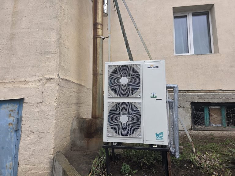
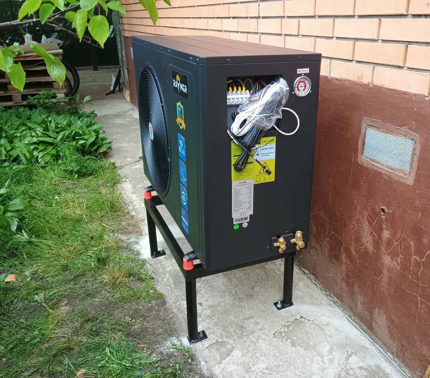
The image shows the process of installing the external unit of the heat pump Raymer RAY-15DS2-EVI. This stage is one of the most important in the implementation of the heating and cooling system, After all, the effectiveness of the equipment and its durability depends on the correct placement and fixation.
The external block is located in the open space near the wall of the building, which provides a free air flow around the fan. The selected place allows you to easily perform service and provides access to electrical connections and freon pipelines.
For installation, a special metal stand was used, stained with protective enamel from corrosion. The design is fixed on a concrete basis, which guarantees its stability during the operation of the heat pump. Additionally, vibroopores are installed under the legs of the stand, which minimize vibrations and reduce noise during operation.
The external unit is firmly fixed to the stand, which ensures its stability even with adverse weather conditions. All mounts were carefully checked for strength, to avoid displacement or loosening during operation.
Features of installation:
- Installation is made taking into account the necessary indentation from the wall, which provides proper air circulation;
- Communications on the outer panel of the block with protective rubber seals were brought up, protecting from moisture and dust;
- All electrical connections are isolated and protected from mechanical damage.
The next step will be the connection of pipelines and freon highways for the circulation of the coolant between the external and internal blocks.
 2. Installation of the RAYMER hydraulic engine
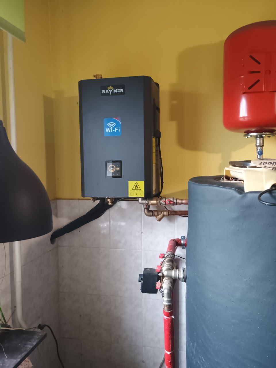
The hydraulic engine was fixed on the wall in a technical room with sufficient ventilation and access for service. The place is chosen like this, To minimize the length of pipelines to buffer capacity and expansion tanks.
For fastening, special brackets with high bearing capacity were used. Fastening is made on a strong wall, which ensures the stability of the structure. The distance from the hydraulic engine to the wall surface was withstanded in accordance with the requirements of the manufacturer to ensure natural ventilation.
The hydraulic engine is connected to the electric network through a separate circuit breaker. This allows you to easily turn off the equipment during service or emergency.
Features of the installation:
- The housing of the hydraulic module has a built-in Wi-Fi module, which allows remote monitoring and management of all processes.
- Connection elements are protected from moisture and mechanical damage.
- There is an indicator of the state of work on the case, which facilitates control over functioning.
 3. Connection of a hydraulic engine to a buffer capacity
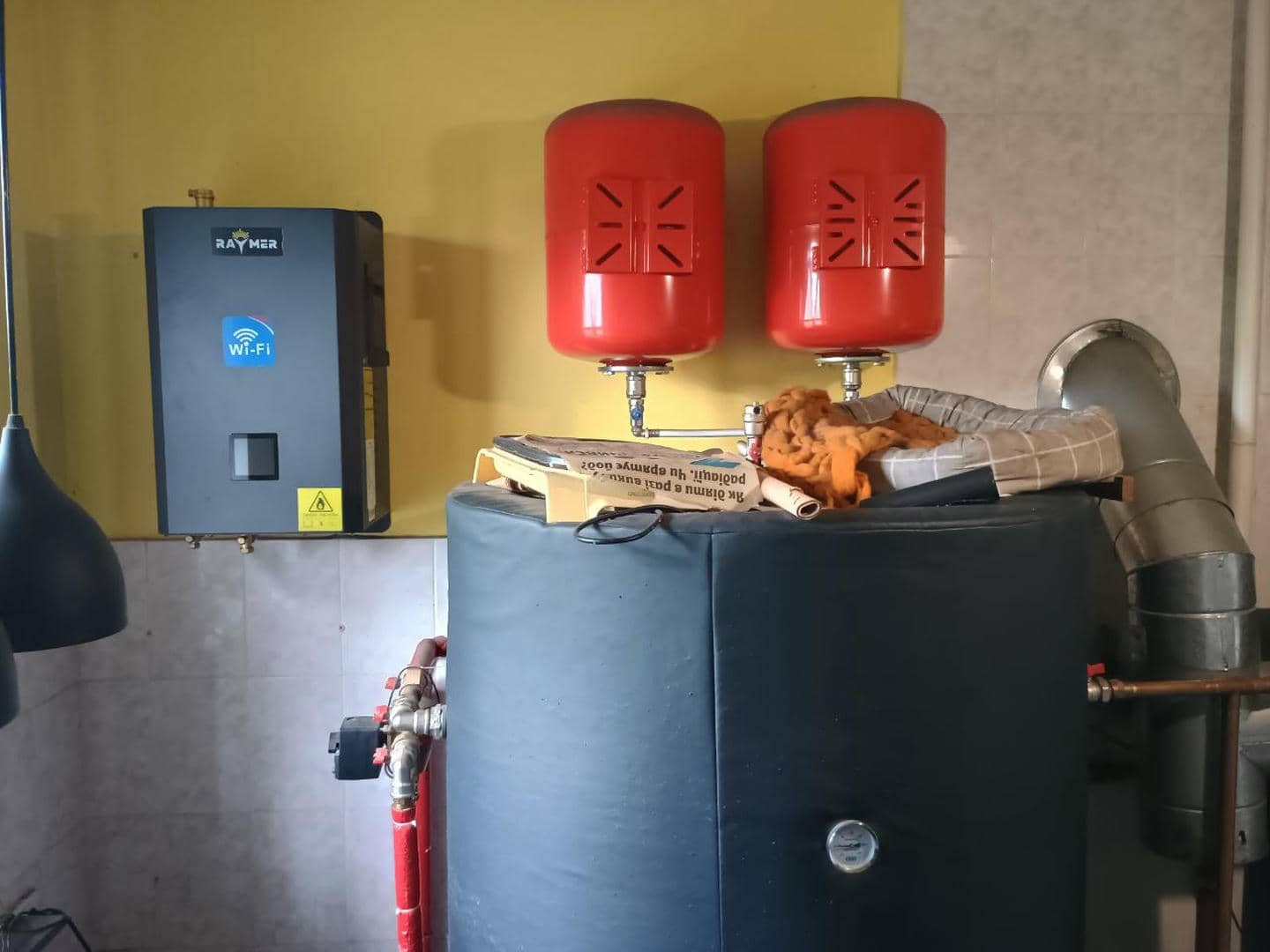
After the successful test launch of the Raymer Ray-15DS2-EVI heat pump, the next step was to connect the hydromodulus to the Raymer IMP buffer capacity. This connection provides stable circulation of the coolant between the heat pump and the internal heating system, and also contributes to the uniform distribution of heat throughout the area of the house.
- The preparation of the necessary materials was carried out: metal -plastic pipes, fittings, insulating materials and ball valves.
- The completeness of the hydraulic engine and buffer capacity is checked, as well as the readiness of the connection points.
- For connection, metal -plastic pipes with a diameter were used 32 mm, providing sufficient throughput.
- At the main points of connection, ball valves are installed, allowing, if necessary, to serve or overlap the contour.
- All compounds are sealed using a special sealing tape and pasta to prevent leaks.
Pipelines, passing through unheated rooms, carefully insulated with special insulating casings. This allows minimizing heat loss when transporting the coolant.
Particular attention is paid to insulation of the joints, to avoid condensation and corrosion formation.
The input and output pipelines are connected directly to the corresponding buffer capacity nozzles.
The circuits of warm floor and radiator heating were also connected.
To ensure uniform supply of the coolant, balancing valves were additionally installed.
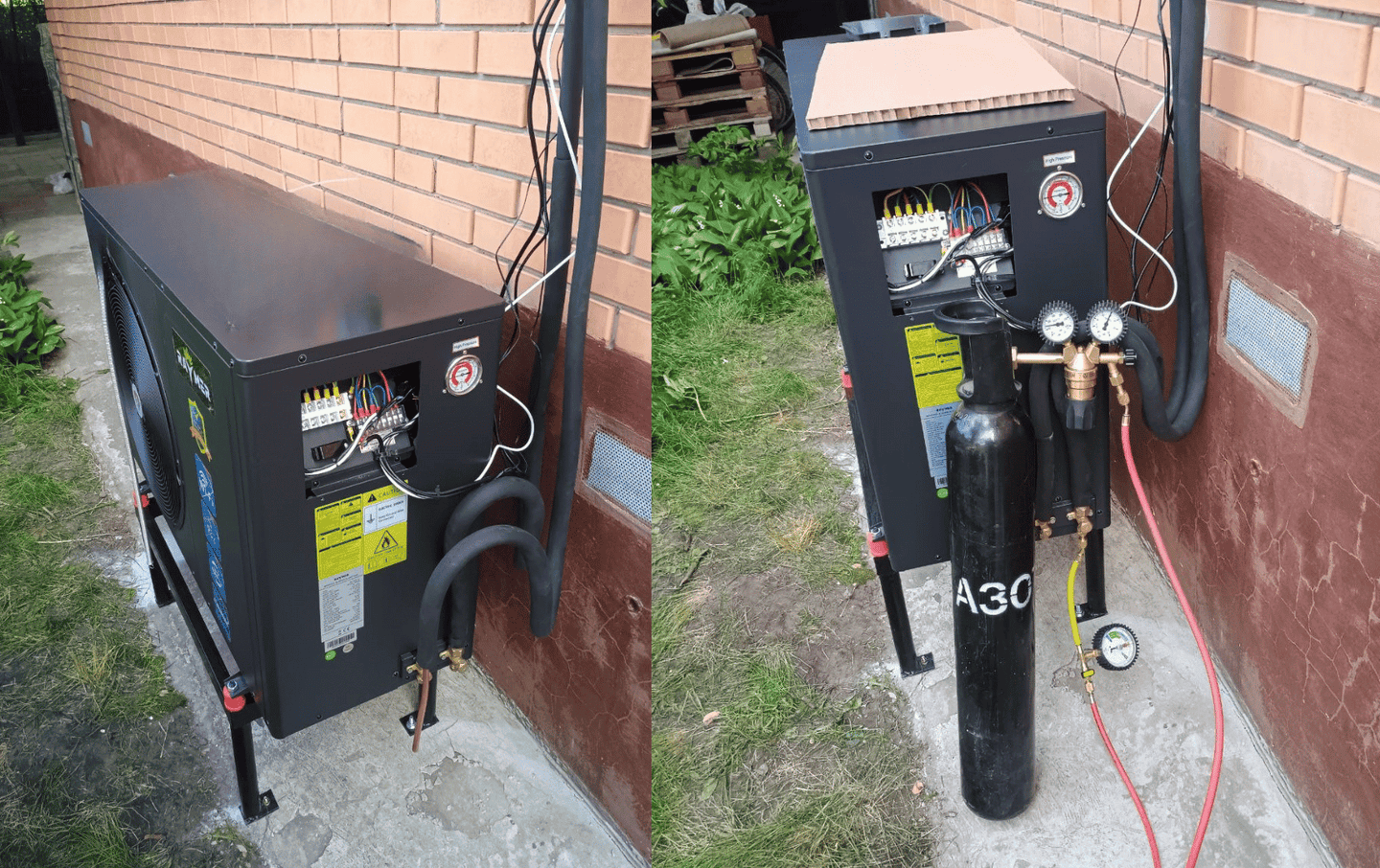
4. Connection Freon highways and Vacuuming the system
After installation External block Raymer Ray-15DS2-EVI And installation hydraulic module, The next step was Connection of freon highways and Vacuuming the system.
Preparation of pipelines:
There were freon highways Pre -prepared: Performed The ends of the ends, Checked cleanliness and absence of moisture. Used Copper pipes with high -quality thermal insulation, which provides effective work Even at extreme temperatures.
Installation of freon highways:
Connection to the external unit and hydraulic engine is made using hermetic fittings. To exclude leaks used High -quality seals and Control of the moment of tightening by using Dynamometric key.
Thermal insulation:
After installation, all pipelines were completely isolated by special materials, to reduce Heat loss and protect from external influence.
Vacuuming the system
Connection of a vacuum station:
On the right side of the image, the process is shown vacuuming. The vacuum station is connected to service ports external block through Special collector.
Vacuuming process:
- Installed Bull with nitrogen for System purges Before vacuuming.
- The system was vacuum to pressure -0,1 MPa (or 100 microns) - Full removal moisture and air From the highway.
- Exposure under the vacuum was about 30 minutes for stabilization of indicators.
Checking test:
After vacuuming, the system was Tested for tightness - Manometers showed stable values.
After successful vacuuming, the system is ready for refueling by freon and test run.
5. Filling and testing the system Raymer Ray-15ds2-EVI heat pump
After completing the installation of pipelines, connection of a hydraulic engine and buffer capacity, The stage began Filling and testing the system - a critical process for Tighting tests and lack of air traffic jams.
1. Preparation for filling out:
- Conducted Visual verification all compounds and fittings.
- Ball cranes are open On the main highways.
- Installed Air valves at the highest points of the system.
2. Filling the coolant:
- The system was filled through Special crane In the lower part of the hydro module.
- Used Pumping station To connect to the feeding line.
- Filling was performed slowly To prevent education air traffic jams.
- They opened at the same time Air valves on buffer capacity and radiators.
3. Checking test:
Runned circulation pump at low speeds for uniform distribution. Conducted Visual check of all connections, including:
- buffer capacity,
- hydraulic module,
- Ball valves and locking reinforcement,
- Freon highways.
Controlled:
- Lack of subtexts.
- The uniformity of the flow without hydraulic boards.
- Air valves.
4. The pumping of the system:
- The pump is on Higher speed - The coolant passed through all circuits.
- Repeatedly open Automatic air valves.
- Additionally checked Higher points systems.
- The system worked for a certain time for stabilization of the flow.
5. Final check and preparation for launch:
- The pressure is brought to work parameters.
- Checked Manometers in all areas.
- All Cranes are fixed In the open position.
- Air valves are left In working condition For the first launch.
Result:
System Successfully filled and Tested on tightness. All compounds reliable, circulation Stable. System ready for the first launch In working mode.